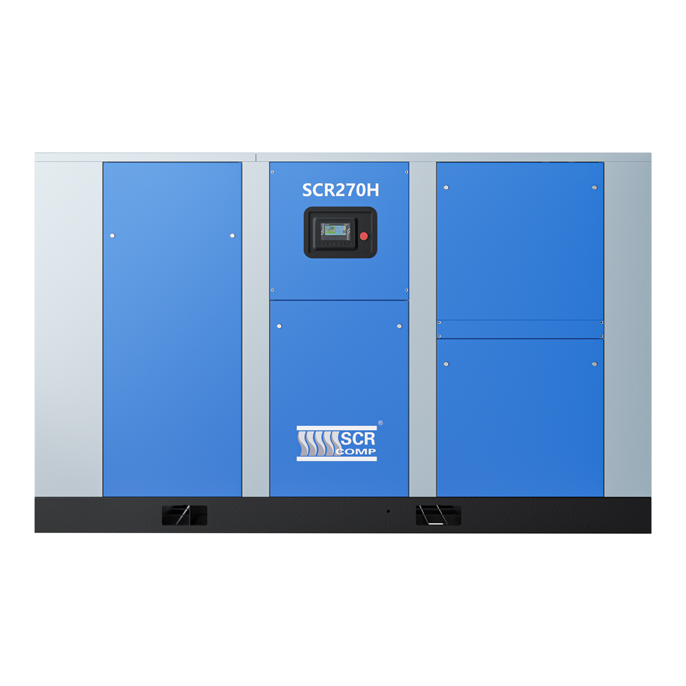
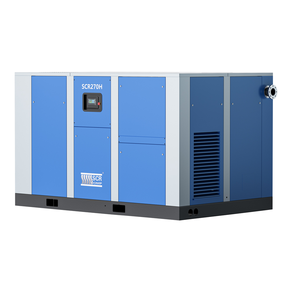
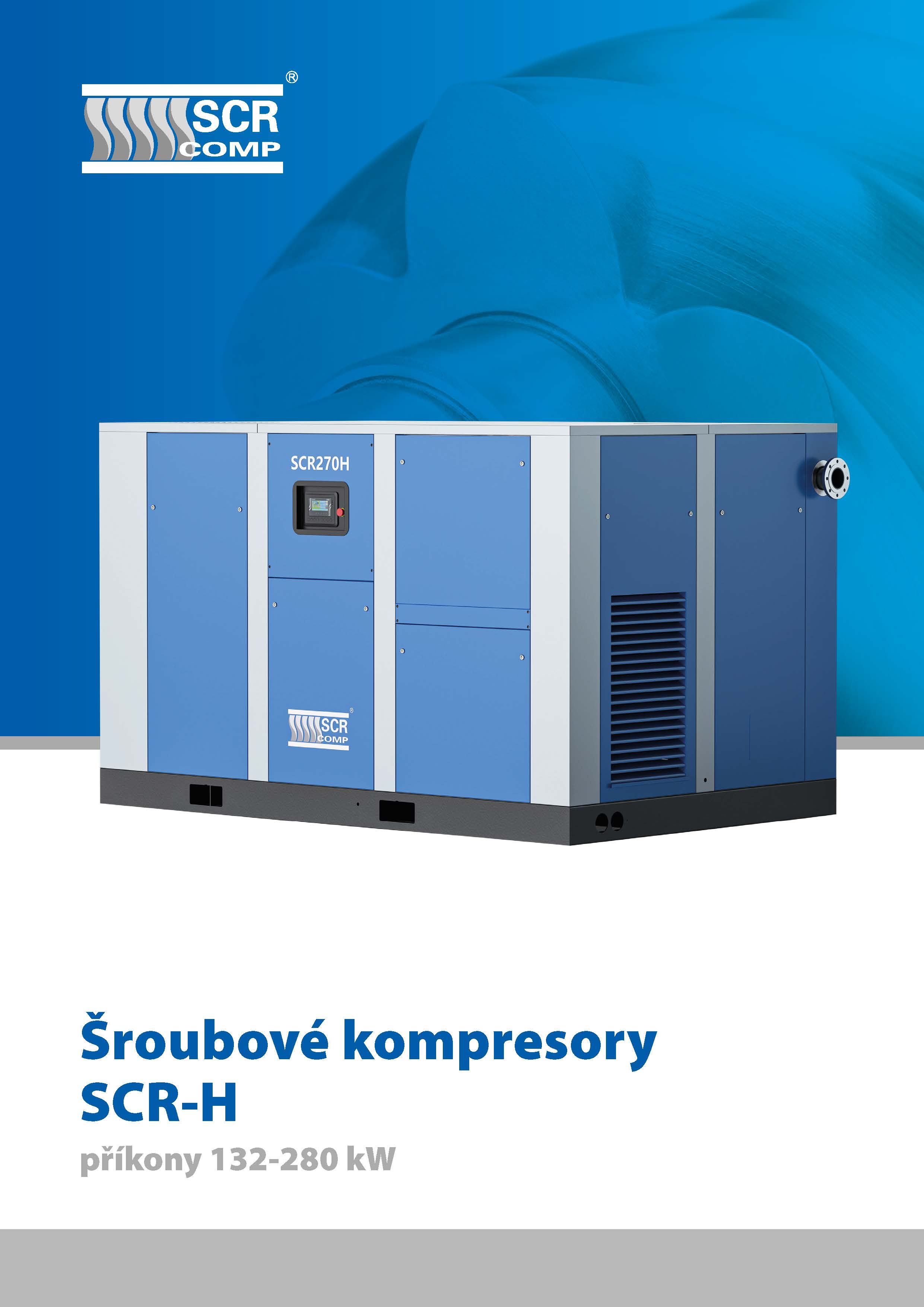
SCR-H Screw compressors
Basic description
- oil-lubricated airend
- two-stage design
- smooth speed control with frequency converter (HPM)
- gearbox drive
- ROTEX elastic coupling
- SCR-9000 electronic controller
- above-standard pressure and temperature measurement options
Pressure versions: 7-8-10-12,5 bar
FAD: 948 to 3 480 Nm3/h
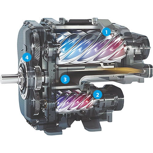
Two-Stage Air Compression
Standard screw compressors use only one airend for air compression. The compression to the required pressure occurs in a single step, known as a stage. The advantage of single-stage compression is a lower price. However, for large volumetric outputs, this method of compression is generally not economical.
During air compression, a significant part of the supplied energy is converted into heat, which reduces efficiency and results in less air being produced compared to the ideal physical process in the so-called isothermal state, where all supplied energy is used exclusively for compressing the gas and no heat is generated.
To achieve higher compression efficiency, two-stage compressors have been developed. They use two airends connected by a gear system, where the air is cooled between the first and second stage, bringing the resulting compression curve closer to isothermal compression.
![]() 1st stage rotors
1st stage rotors
![]() cooling space
cooling space
![]() 2nd stage rotors
2nd stage rotors
![]() gearbox
gearbox
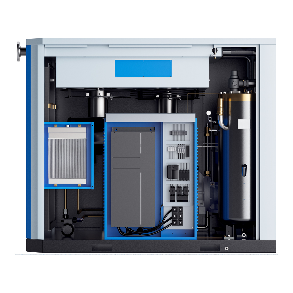
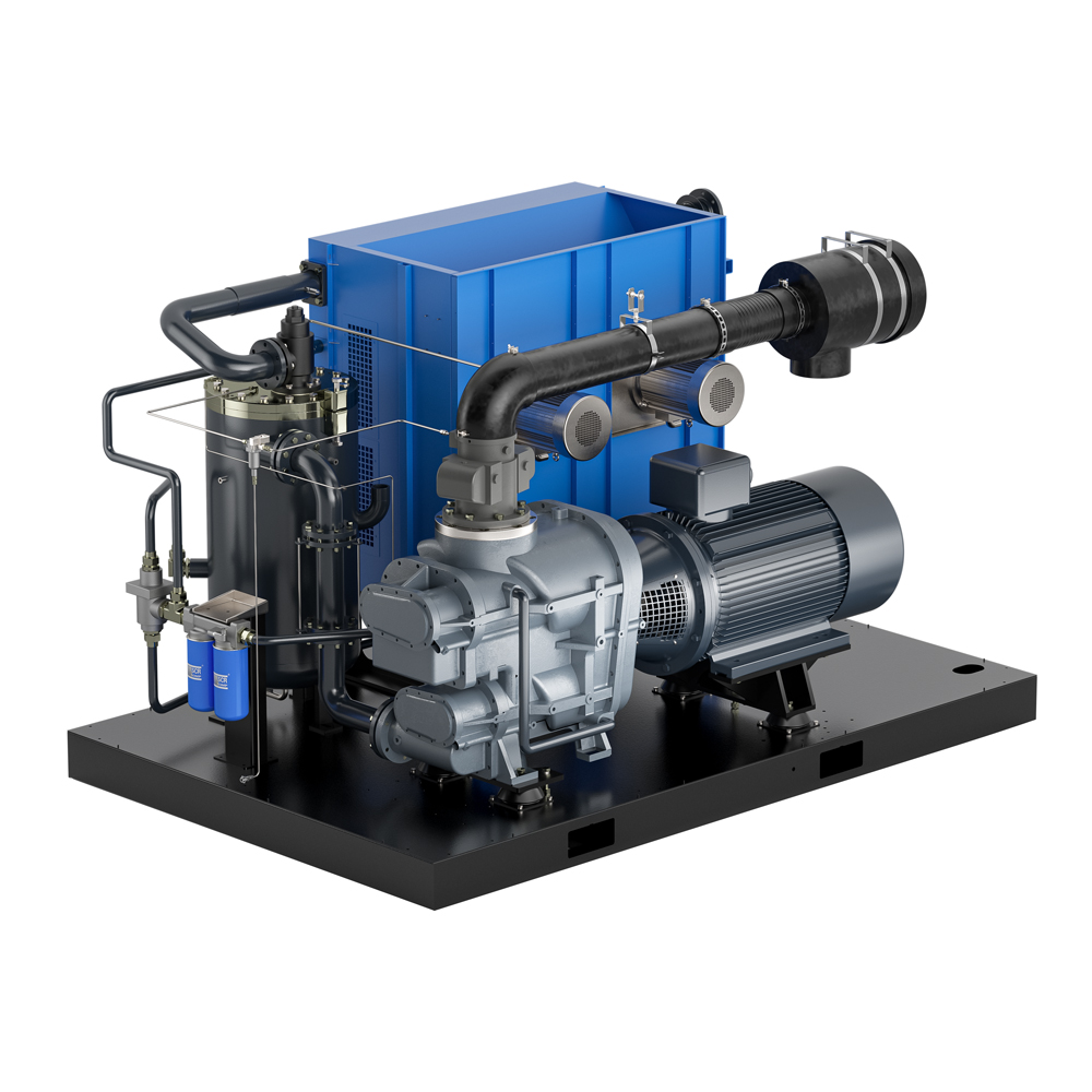
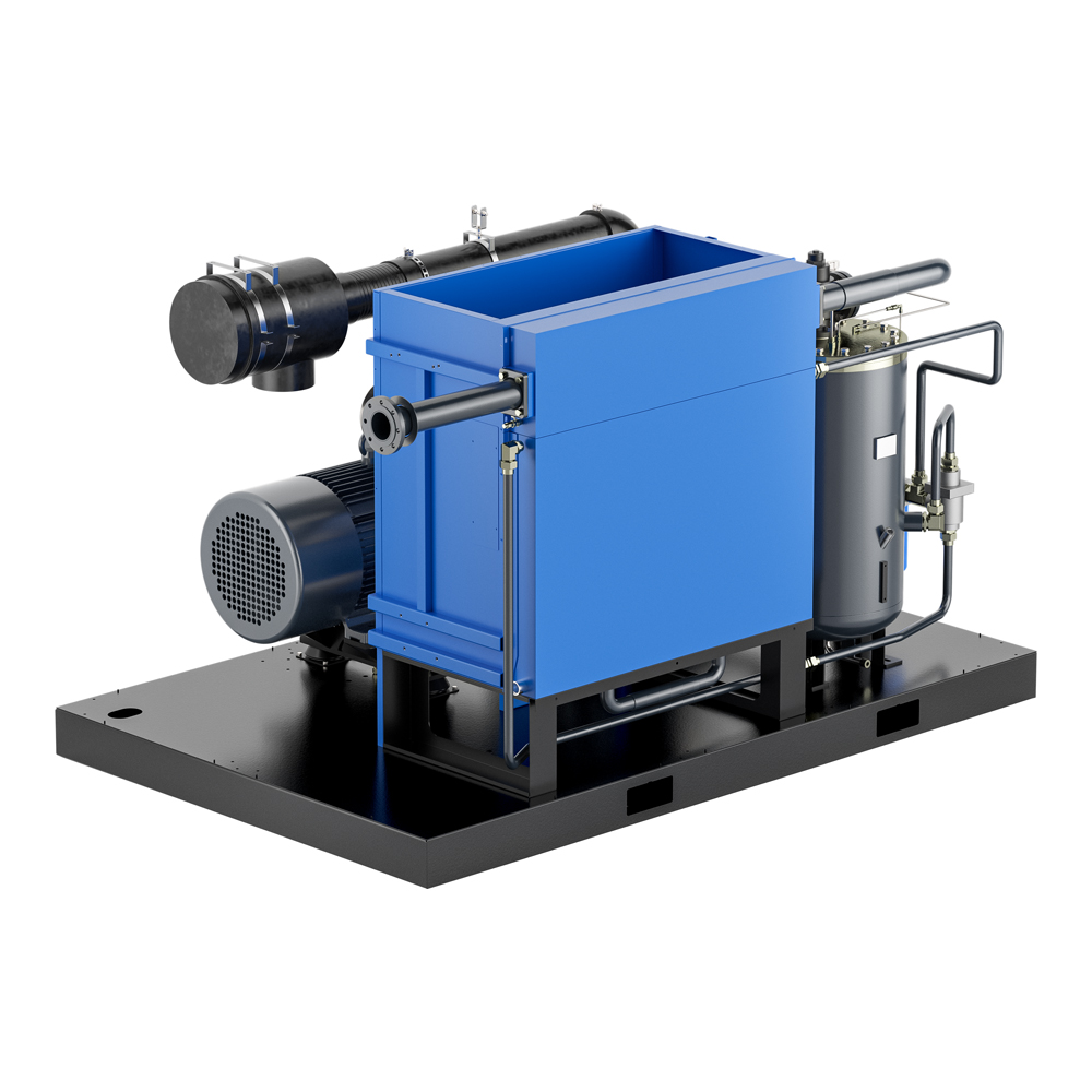
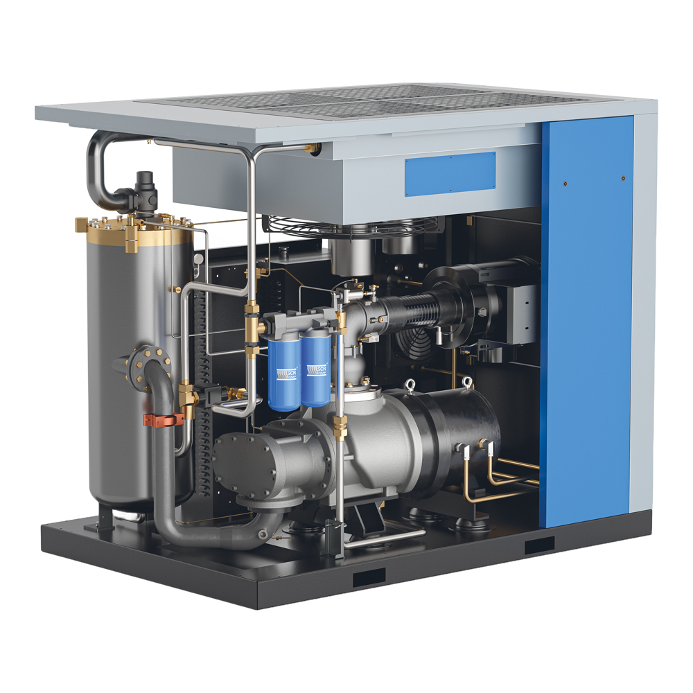
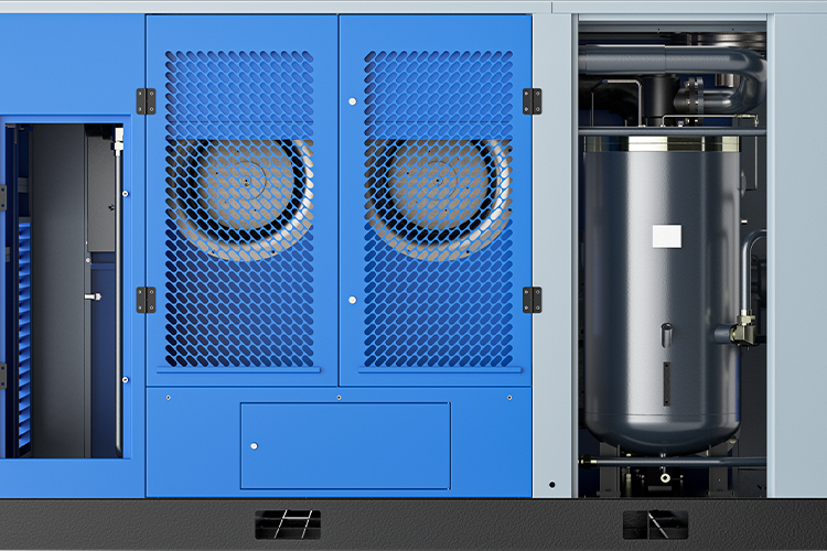
Machine design
The design of the individual parts of the SCR-H compressors is such that the interior of the compressor is optimally cooled and, at the same time, good service access to all important components is ensured.
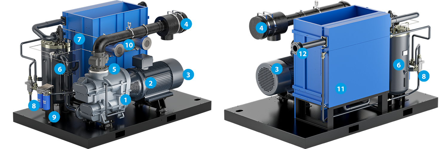
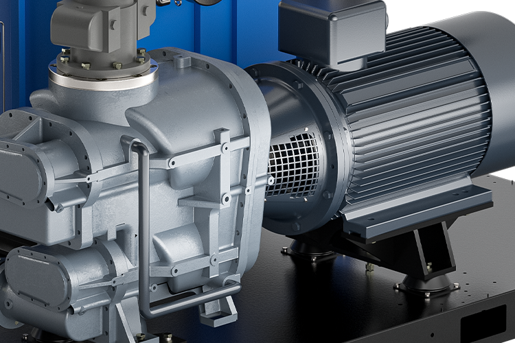
![]() airend with gearbox
airend with gearbox
![]() flexible coupling
flexible coupling
![]() electric motor
electric motor
![]() air filter
air filter
![]() intake valve
intake valve
![]() oil reservoir
oil reservoir
![]() minimum pressure valve
minimum pressure valve
![]() thermostatic valve
thermostatic valve
![]() oil filters
oil filters
![]() fan motor
fan motor
![]() radiator
radiator
![]() air inlet
air inlet
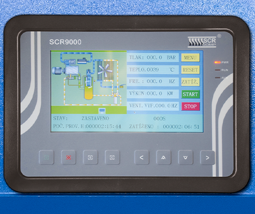
SCR9000 electronic controller
A modern system for controlling screw compressors with a convenient 7" colour touch screen and the following functions and features:
- button control
- display of all necessary machine operating parameters
- indication of operating warnings and alarms
- alarm history for machine fault analysis
- User level via password
- practical display of electricity consumption
- weekly plan with 5 time slots for compressor start-up and shutdown
- Automatic restart after power failure
Compressors with Variable Speed Control (SCR-HPM)
Traditional fixed-speed compressors operate in work cycles where the compressor alternates between loaded operation, unloaded operation, or being completely stopped. Immediately after starting, air compression begins and the main motor runs under load. Once the required pressure is reached, the compressor switches to unloaded operation, where it no longer produces air but the motor continues to rotate the airend at idle, consuming energy.
Unloaded operation makes the next restart easier, but during these several seconds, unnecessary energy consumption occurs, typically amounting to tens of percent of the total energy used. The lower the air demand, the higher the proportion of unloaded operation, creating an opportunity for significant savings in the cost of compressed air and overall operating expenses associated with the compressor.

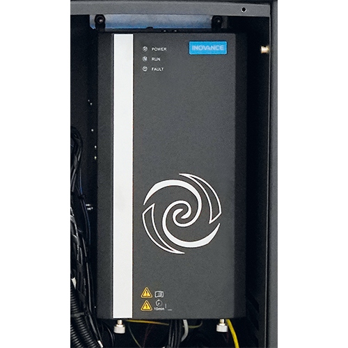
Frequency converters with vector control
SCR-HPM compressors are equipped with advanced INOVANCE frequency converters that maintain the required output pressure and adjust the drive speed to the immediate demand for compressed air. Thanks to this modern control system, idle running is significantly reduced, resulting in energy savings of tens of percent. Further cost reductions can be easily achieved by quickly adjusting the output pressure and control pressure range.
The vector-controlled converters used have been developed specifically for screw compressor applications and provide very high torque at frequencies as low as 0.1 Hz. Standard frequency converters either cannot operate below 5 Hz or are extremely inefficient in this range.
The new generation of INOVANCE vector converters ensures very high energy efficiency across the entire speed range.
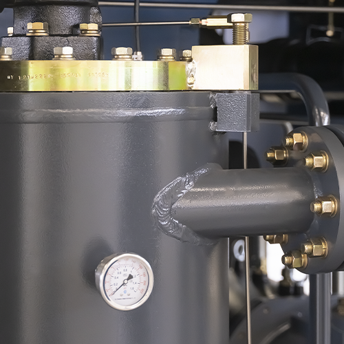
Oil reservoir
With a practical swivel cap, glycerine pressure gauge and oil gauge.
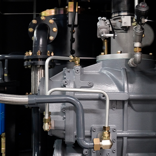
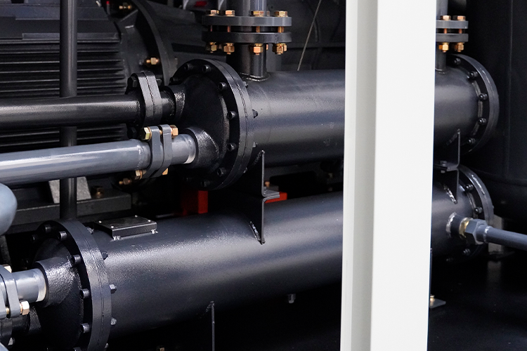
Metal fluid connections
All air and oil connections are made with pipes and steel hoses.
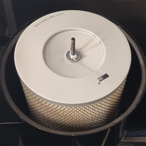
Air filter
Highly robust design with 99.5% efficiency, doubled for increased protection of the airend.
Clutch
A high-quality ROTEX flexible coupling from German manufacturer KTR is used to connect the electric motor to the gearbox.
Fans
The compressors use powerful fans for perfect machine cooling. In the SCR-HV design, one of the fans is equipped with speed control.
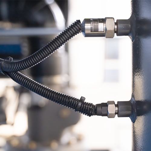
Sensors
The compressors are equipped with above-standard temperature and pressure sensing capabilities.
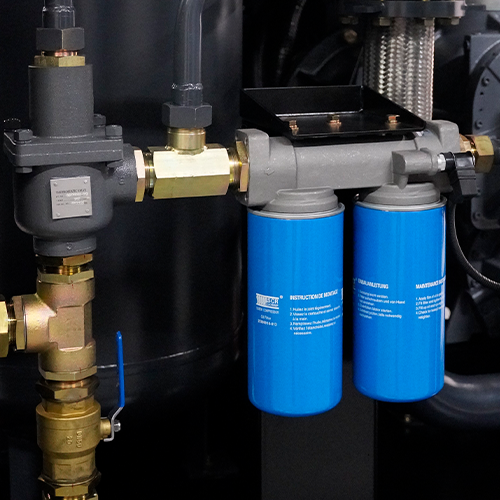
Oil filters
Serial arrangement for optimal filtration of oil from solid impurities and with pressure drop detection.
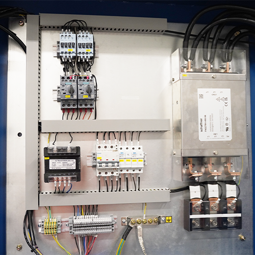
Electrical switchboard
Equipped with top-of-the-line components from SIEMENS with high reliability.
Optional variants
All two-stage screw compressors in the SCR-H series can also be supplied with optional extras that further improve their performance.
Water cooling
for increased compressor efficiency and reduced machine noise.
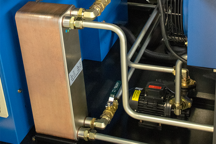
Heat recovery
uses heat from the compressor to heat domestic water using a water-oil exchanger.
Technical data (SCR-H - fixed speed)
| Machine model | Power (kW) |
Pressure (bar) |
FAD output (Nm3/h) |
Output | Noise level [dB(A)] |
Dimensions (L × D × H) |
Weight (kg) |
|---|---|---|---|---|---|---|---|
| SCR-132/7H | 132 | 7 | 1710 | DN 80 | 82 ± 3 | 3400 × 2100 × 2000 | 4700 |
| SCR-132/8H | 8 | 1680 | |||||
| SCR-132/10H | 10 | 1350 | |||||
| SCR-132/12H | 12,5 | 1110 | |||||
| SCR-160/7H | 160 | 7 | 1980 | DN 80 | 82 ± 3 | 3400 × 2100 × 2000 | 4900 |
| SCR-160/8H | 8 | 1968 | |||||
| SCR-160/10H | 10 | 1650 | |||||
| SCR-160/12H | 12,5 | 1380 | |||||
| SCR-185/7H | 185 | 7 | 2340 | DN 100 | 84 ± 3 | 3400 × 2200 × 2100 | 5800 |
| SCR-185/8H | 8 | 2310 | |||||
| SCR-185/10H | 10 | 2040 | |||||
| SCR-185/12H | 12,5 | 1740 | |||||
| SCR-200/7H | 200 | 7 | 2580 | DN 100 | 84 ± 3 | 3400 × 2200 × 2100 | 6000 |
| SCR-200/8H | 8 | 2520 | |||||
| SCR-200/10H | 10 | 2340 | |||||
| SCR-200/12H | 12,5 | 1980 | |||||
| SCR-220/7H | 220 | 7 | 2748 | DN 100 | 84 ± 3 | 3400 × 2200 × 2100 | 6600 |
| SCR-220/8H | 8 | 2730 | |||||
| SCR-220/10H | 10 | 2520 | |||||
| SCR-220/12H | 12,5 | 2250 | |||||
| SCR-250/7H | 250 | 7 | 3090 | DN 125 | 86 ± 3 | 4000 × 2200 × 2300 | 7000 |
| SCR-250/8H | 8 | 3060 | |||||
| SCR-250/10H | 10 | 2760 | |||||
| SCR-250/12H | 12,5 | 2430 | |||||
| SCR-280/7H | 280 | 7 | 3720 | DN 125 | 86 ± 3 | 4000 × 2200 × 2300 | 7400 |
| SCR-280/8H | 8 | 3660 | |||||
| SCR-280/10H | 10 | 3060 | |||||
| SCR-280/12H | 12,5 | 2760 |
The FAD performance is measured according to ISO 1217 and is specified at the maximum pressure of the given model. Additional FAD performance values at different pressure levels are available in technical data sheets upon request. The noise level is measured at a distance of 1 meter from the machine.
Technical data (SCR-HPM with speed control)
| Machine model | Power (kW) |
Pressure (bar) |
Min. FAD output (Nm3/h) |
Max. FAD output (Nm3/h) |
Output | Noise level [dB(A)] |
Dimensions (L × D × H) |
Weight (kg) |
|---|---|---|---|---|---|---|---|---|
| SCR-132/7HPM | 132 | 7 | 516 | 1710 | DN 80 | 82 ± 3 | 3400 × 2100 × 2000 | 4900 |
| SCR-132/8HPM | 8 | 504 | 1680 | |||||
| SCR-132/10HPM | 10 | 405 | 1350 | |||||
| SCR-132/12HPM | 12,5 | 333 | 1110 | |||||
| SCR-160/7HPM | 160 | 7 | 594 | 1980 | DN 80 | 82 ± 3 | 3400 × 2100 × 2000 | 5100 |
| SCR-160/8HPM | 8 | 588 | 1968 | |||||
| SCR-160/10HPM | 10 | 498 | 1650 | |||||
| SCR-160/12HPM | 12,5 | 414 | 1380 | |||||
| SCR-185/7HPM | 185 | 7 | 702 | 2340 | DN 100 | 84 ± 3 | 3400 × 2200 × 2100 | 6200 |
| SCR-185/8HPM | 8 | 696 | 2310 | |||||
| SCR-185/10HPM | 10 | 612 | 2040 | |||||
| SCR-185/12HPM | 12,5 | 522 | 1740 | |||||
| SCR-200/7HPM | 200 | 7 | 774 | 2580 | DN 100 | 84 ± 3 | 3400 × 2200 × 2100 | 6400 |
| SCR-200/8HPM | 8 | 756 | 2520 | |||||
| SCR-200/10HPM | 10 | 702 | 2340 | |||||
| SCR-200/12HPM | 12,5 | 594 | 1980 | |||||
| SCR-220/7HPM | 220 | 7 | 840 | 2748 | DN 100 | 84 ± 3 | 3400 × 2200 × 2100 | 7100 |
| SCR-220/8HPM | 8 | 840 | 2730 | |||||
| SCR-220/10HPM | 10 | 780 | 2520 | |||||
| SCR-220/12HPM | 12,5 | 660 | 2250 | |||||
| SCR-250/7HPM | 250 | 7 | 930 | 3090 | DN 125 | 86 ± 3 | 4000 × 2200 × 2300 | 7000 |
| SCR-250/8HPM | 8 | 918 | 3060 | |||||
| SCR-250/10HPM | 10 | 828 | 2760 | |||||
| SCR-250/12HPM | 12,5 | 732 | 2430 | |||||
| SCR-280/7HPM | 280 | 7 | 1020 | 3720 | DN 125 | 86 ± 3 | 4000 × 2200 × 2300 | 7400 |
| SCR-280/8HPM | 8 | 960 | 3660 | |||||
| SCR-280/10HPM | 10 | 840 | 3060 | |||||
| SCR-280/12HPM | 12,5 | 690 | 2760 |
The FAD performance is measured according to ISO 1217 and is specified at the maximum pressure of the given model. Additional FAD performance values at different pressure levels are available in technical data sheets upon request. The noise level is measured at a distance of 1 meter from the machine.
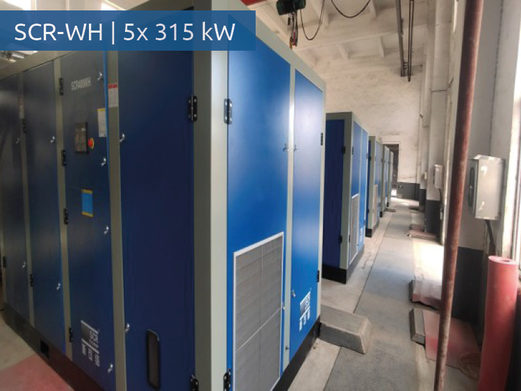
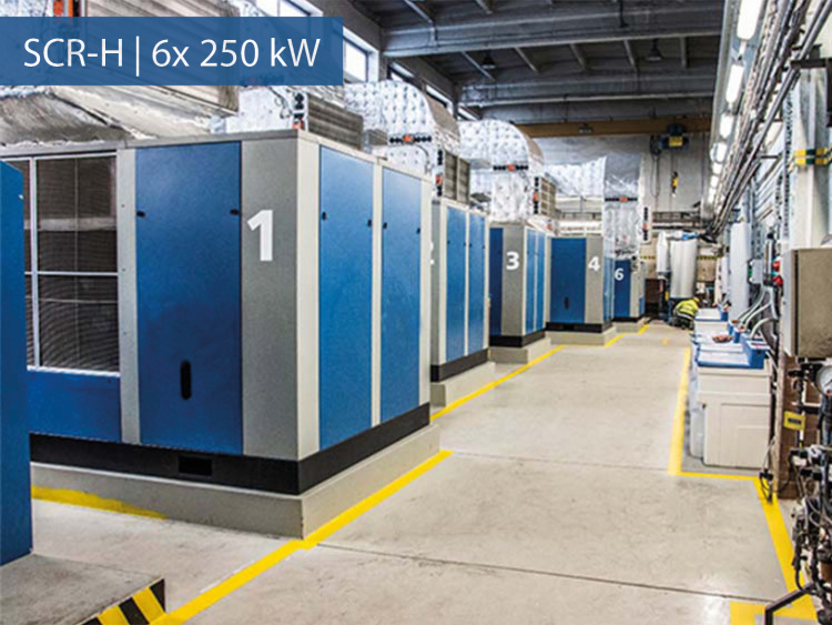
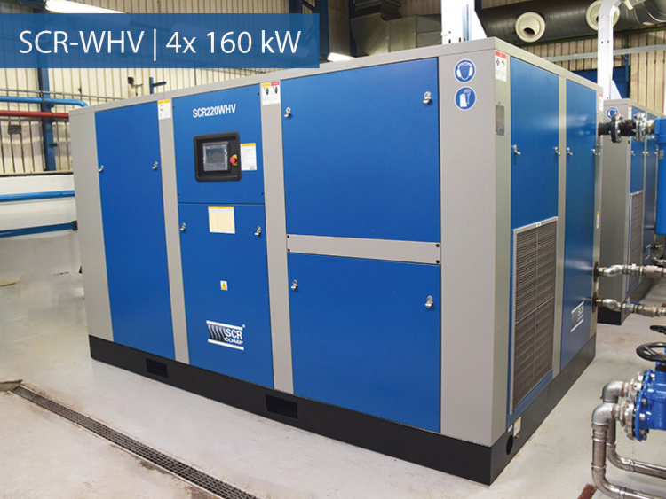
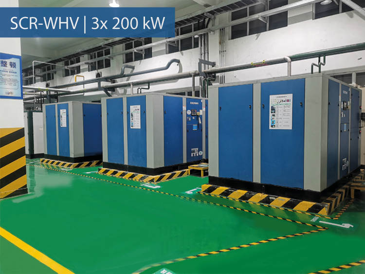
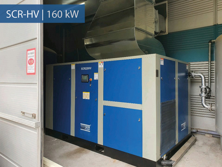
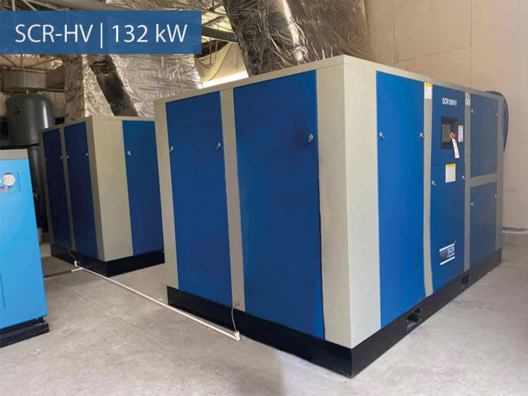
Installation examples
Thousands of two-stage SCR-H series screw compressors are subjected to the most rigorous testing every day in industrial and energy applications, including climatic conditions with extremely high temperatures and humidity. The SCR brand has a long history of successful projects and experience with compressor stations with a total power output of several MW.